There is a growing expectation for component manufacturers to create product designs in three dimensions. 3D CAD (computer-aided design) software is utilized by nearly every equipment manufacturer in nearly every industry. The 3D modeling has cut testing and production times significantly, allowing simulated testing (such as FEA, finite-element analysis) and prototyping to occur virtually before physical development takes place.
Beyond the time it saves in prototyping multiple iterations of the same design, it saves on materials costs—no more wasted materials on two or three prototypes that weren’t quite right. Especially in today’s reduced-man-power economic climate, companies have had to learn to do more with less. Time and cost savings are essential to keeping manufacturing companies profitable and progressive.
Dassault Systèmes SolidWorks Corp. (SolidWorks), Concord, MA, serves a user pool of over 1.5 million product designers and engineers worldwide with its 3D design software tools for design, simulation and product management. “It’s getting to the point where designers and engineers will only buy their off-the-shelf components from companies that also supply them with the 3D CAD models of their products. 3D models are that important now,” says Craig Therrien, product manager for SolidWorks.
Its latest announcement, the new SolidWorks 2012 with industry-first automated cost estimation feature, takes the benefits of 3D design one step further, allowing more manufacturing cost and time savings during the design process.
Reducing costs with 3D CAD design
When people are quoting on a job, “and this is a trend I see across all industries— automotive, machine design, heavy equipment—right now, they are often not actually quoting, but responding to what they will provide in order to hit a particular price target. In other words, we can provide this, for that particular amount of money you want to pay," explains Therrien. Companies are looking for ways to make their profit margin, but continually have to find ways to design and manufacture better and cheaper. “Companies have to reduce cost, and the cost of manufacturing their products is a key area they are targeting.” Setting cost targets to hit, instead of asking how much will it cost to produce a design, is becoming a trend cost conscious companies are using to make sure cost targets they set early in a project are carried through to final manufactured product.
To help in reducing costs associated with manufacturing, many manufacturers have moved toward 3D CAD systems, and away from traditional, older 2D CAD systems. There are many advantages of 3D CAD, here are some of the main advantages.
First is the ability to more clearly visualize and communicate your design ideas with customers, colleagues and manufacturing because 3D provides a life-like, photo-realistic and interactive design experience you cannot get with a 2D drawing. Many manufacturers have moved to 3D as a way of selling and marketing their products as well as designing and manufacturing. Presenting a design in 3D vs. a 2D drawing gives companies a distinct advantage.
Second, you can automatically check and fix interferences and collisions between components and even fasteners in your design before going to manufacturing.
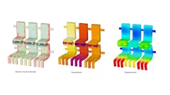
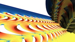
Third, the ability to virtually prototype your product in action, subjecting your design to the forces and motions that it would experience in real life, allows you to reduce or even eliminate the need to create physical prototypes. "Simulation equals cost savings,” Therrien says.
Virtual prototyping, a trend that grows approximately 10 to 15% per year as shown in sales of simulation software. Even during the recession in 2009, sales of SolidWorks simulation software maintained its 2008 numbers demonstrating that people were buying and using virtual prototyping because they literally could not afford to physically prototype.
Fourth, the ability to create production quality drawings in which all the drawing views are always correct and in-synch with the 3D design model – you never have to worry about drawing views that are incorrect, and the scale is always accurate.
Fifth, the ability to automate your design processes and improve standardization and reuse of existing components. SolidWorks has the ability to do more than just simulate a design, by allowing designers and engineers create multiple design configurations quickly. The software allows a designer to go in to a design and vary any dimensional parameter or feature. “You can make as many iterations as you want off of one model, you don’t have to remodel it.” The variations can range from the way the design is manufactured, what components are included, the materials used, or even the color.
A designer could go in and quickly make a change for different equipment model sizes, such as adjusting track length, the size of the wheels, cylinder length or bucket size. The software also has automated programming capabilities that allow a user to program the software to adjust the number of bolts dependent on the flange diameter. “As the diameter of the flange increases, the software automatically adds more bolts and bolt holes,” Therrien says.
And sixth, you have the option of sending 3D CAD models directly to NC programming for manufacturing.
And finally, when a design change happens, your drawings, BOM’s and even your NC programming data can be updated automatically. You don’t have to waste precious design time reworking drawing views, updating BOM’s or even redoing NC toolpaths, just because the design changed.
Designing for Cost
One aspect of product development that has always eluded companies is how to design a product to hit a particular cost target. Efforts are centered around cross-functional teams consisting of designers, engineers, manufacturers and purchasing working together throughout the design to figure out the best ways to reduce the cost of the product. Typically, these efforts have focused on redesigning an existing product for cost. But is there a better way, a way to capture and track manufacturing costs during the design phase. A way that would allow an engineer to understand when he is exceeding his cost target so he can make corrections today before the design gets to manufacturing.
Two of the key roadblocks to being able to design for cost in the initial design phase are:
- Designers typically must rely on internal or external manufacturing sources for accurate cost data for their designs, or must manually calculate the cost estimates using spreadsheets or some other method
- Designers need to move ahead and get the final design out the door, waiting for quotes, or processing quotes themselves is time consuming
According to customer surveys conducted by SolidWorks, approximately 90% of of their customers claim their biggest problem with cost quoting and estimating is the time it takes. Although repeatability and accuracy are next on the list, speed of quoting is most painful. And time is something in short supply when you are talking about the product development cycle.
Driven by shortened development cycles, lead time reduction has become one of the top competitive advantages for component suppliers, especially when competing with foreign companies with cheaper labor and materials costs. Manufacturers are finding that with the right amount of cost and time reduction during the design phase, they can win contracts without having to outsource overseas. If the local supplier can get the right price point, it may not beat the price of a foreign competitor, but are low enough so the other hassles of oversea component purchasing is outweighed.
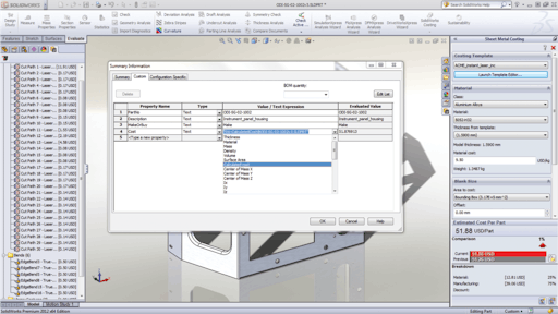
Suppliers across the board are experiencing tighter margins, and SolidWorks 2012 will offer Costing, a software feature that allows the designer to automatically see how much the part will cost to manufacture as it is being designed. Every time the designer or engineer makes a product design change, a new cost to manufacture the part is automatically calculated and displayed on the screen. The manufacturing information needed to calculate costs such as raw material costs, labor rates, and machine tool speeds and feeds are automatically extracted from manufacturing templates provided by SolidWorks. These manufacturing templates are easily customized thereby allowing companies to simulate their own internal manufacturing processes and costs, or those of their external manufacturing vendors. “The trend I see is that manufacturers are working more closely with their design customers, sharing their manufacturing expertise and even manufacturing cost information to help their customers design for manufacturing cost—it’s a win-win situation,” says Therrien.
The two processes SolidWorks’ customers deal with most often are sheet metal manufacturing and machining. The heavy equipment industry tends to work with a lot of heavy plate and heavy welded pieces. “For sheet metal and plate we support operations such as laser, water jet and plasma cutting as well as bending and punching. And for machining, it’s mainly mill and drill operations right now,” Therrien says. A sheet metal costing product and a machine part costing product are the first two processes released, with more to follow through the years.
Companies with internal manufacturing capabilities want their engineering and manufacturing departments to work together seamlessly. “What typically happens are things get over-designed, cost too much and then later need to be redesigned to meet a lower price point,” says Therrien. “The Costing tool provides manufacturing cost templates that can be modified and saved to match the manufacturing processes of a specific shop. The templates are easy to edit—they’re like spread sheets—set it up once and you can costs as many parts as you like automatically. While the engineer is designing, the Costing tool constantly looks at the geometry of the part, figures out what processes are needed to manufacture it and updates the cost estimate automatically right there in SolidWorks.”
For the manufacturer, SolidWorks’ Costing feature offers a fast quoting tool. “During our software quality testing of Costing, one of our manufacturing test companies saw that the time they spent creating estimates dropped from about 5 hours a day, to about 40 minutes,” says Therrien.
A designer can see cost adding up as the design is in progress, and allows the component to be redesigned immediately, before it goes to manufacturing, if it is tracking to be too costly. According to a survey conducted by SolidWorks, approximately 85% of the estimating is done by engineers and designers, with only about 10% of SolidWorks users having dedicated purchasing departments to handle quoting.
The Costing tool allows a designer with a target price point to change a few characteristics of their design such as material used, or specific features of the design, in order to reduce the manufacturing cost.to offer multiple quotes very quickly. Therrien offers an example, “A designer thinks customer wants a part designed with carbon steel will save cost, but then has to paint the part to avoid rust. When he selects to add paint, a feature which can be accounted for automatically with SolidWorks Costing, he finds that the cost increases significantly due to the paint operation. He tries switching the material to stainless and eliminating the paint operation and finds a significant cost savings from the painted part. The customer is happy and the engineer was able to make a design decision almost instantly without having to go out for a quote, ask someone in manufacturing or manually measure surface area of the part, look up paint costs, setup costs and other information.
System creation and integration simplified
SolidWorks has partnered with control system companies National Instruments and Rockwell Automation to develop a way to share information more easily. Typically mechanical, electrical and controls engineers have a hard time communicating due to the fact that they are using different design systems. The information between these groups is often shared as written documents or just word of mouth. Through their work with National Instruments and Rockwell Automation SolidWorks users can now share important information about their designs, automatically with controls and electrical engineers. Information such as the motion, mass, and moments of inertia can be extracted automatically from SolidWorks and fed into controls programs that help in the selection and design of motion systems including things like actuators and motors.
In addition, the mechanical aspects of motion systems can now be optimized faster to fit existing components such as motors and actuators. System adjustment due to the fact that you may have to use specific electrical components, such as having to make do with a 12 volt motor when a 24 volt is required for a boom design, is less of a headache. By plugging in the 12 volt motor as a fixed value, the designer can adjust boom material and weight to make the design work within its parameters.
“We call that picking a control system and optimizing the design automatically to work within that control system’s requirements. You can tell the program which parameter values to allow variance, then run several optimization routines to find the best design,” Therrien says.
This feature coincides with struggles component manufacturers are confronting with the changing engine system and how their product reacts with the new system functions. The engine values can be fixed, allowing the program to run instances to find ways to optimize component design to work with the engine.
“This new type of optimization we do is to optimize your mechanical design to work with your electrical or hydraulic system, basically,” he says. The software doesn’t care what type of system, it only cares about the system specifications—the torque, the speed or accelerations of a component or system.
Performance-based design
A typical heavy-duty equipment manufacturer is building an extremely complex, oftentimes extremely large machine with hundreds of components for just one section or system. A 3D CAD system needs to be able to handle the large number of 3D component models needed to make up a complete system design without slowing down the program or computer.
Designs have gotten bigger and more complex, and designers want to put more on the screen. In SolidWorks 2012, Large Design Review allows more data to be viewed faster. With Large Design Review, even massive assemblies, consisting of thousands of components, can be opened in and viewed in seconds. The models can be edited, sectioned, measured and you can even fly-through your designs to get a sense of what it’s like inside your design, say for instance inside the cab of an earth mover.
A slow running program means a design engineer isn’t able to perform at peak output. “Every year, it seems that the number of parts goes up, never down. So we need to continually be improving the performance of our software to accommodate the growing demand of designers,” says Therrien. “If the system is slow, that’s just delaying the development cycle.”
It’s not just about making drawings anymore.
All of the product enhancements to SolidWorks’ products are about reducing time and cost, while at the same time improving quality. “It’s about making better use of the CAD data that’s available to you. What we’re trying to provide are applications that will allow an engineer to make better use of the CAD data to reduce time spent doing his entire job, not just modeling and making drawings, but also on operations like estimating, part search or design review,” says Therrien.
The more a manufacturer can work with its vendors, the quicker product can be turned around. 93% of Therrien’s customers claim their biggest problem with cost quoting and estimating is the time it takes. Not accuracy. Not repeatability, but that the process is too slow.
Lead time reduction has become one of the top competitive advantages for component suppliers, especially when competing with foreign companies with cheaper labor and materials costs. Manufacturers are finding that with the right amount of cost and time reduction during the design phase, they can win contracts without having to outsource overseas. If the local supplier can get the right price point, it may not beat the price of a foreign competitor, but are low enough so the other hassles of oversea component purchasing is outweighed.
Integrated CAD to CAM
Heavy equipment designers and manufacturers have to get design right the first time which is why they love detailed drawings. The “production drawing” capabilities of SolidWorks, as Therrien calls them, allows the designer to go in and create any view, and quickly annotate any drawing quickly and exactly the way he wants it to look. But beyond drawings is the question, how do I actually turn my design data into a manufactured parts?
In most cases companies turn to CAM (computer-aided manufacturing). When it comes to machining, 3D CAM programs that can accept 3D CAD models directly save time and eliminate errors and rework. If a 3D CAD model can be read directly into a 3D CAM program, time is saved by not having to recreate that data in the CAM system, and not having to export an intermediate file. When a CAM system is fully integrated with a CAM system things get even more efficient. In a fully integrated CAD and CAM environment, any change that occurs in the design model can be automatically picked up by the CAM system. In other words, update the design model and the CAM model updates also automatically.
Currently the company has seven Gold CAM partners that are fully integrated with the SolidWorks CAD software. For instance, Mastercam CAD/CAM provides a version of their product that runs completely inside SolidWorks. “The advantage of that is as you’re designing the part, any changes you make will automatically be updated in the CAM program,” says Therrien. “The metrics are showing some customers are seeing as high as 90% decrease in their cycle times because they don’t have to worry about translating the data, and because they have automated their design through manufacturing process. Typically customers see up to 40% decrease, mainly due to not have to translate and repair data everytime a design change occurs.”
The importance of intuitiveness
SolidWorks also found that its products needed to be easy to learn and use. “Many of our customers come from 2D products. Intuitiveness and ease of use are essential. That means two things,” explains Therrien. “One, if I’m a new user, how fast can I get up to speed on the new software so it doesn’t affect my productivity. Two, once I get good at using the 3D system, how much faster can I get? Are there ways to speed up what I’m doing?”
System intuitiveness is a key element to SolidWorks software creation to make features easy to find. Back in 1995, SolidWorks was the first major CAD company to launch a software interface based on the Microsoft® Windows® system platform to give new users a sense of system familiarity.
It was important to the company for its software to focus not just on the software geometry or the number of features it could give operators, but rather the experience the operator was going to have with the SolidWorks product.
The SolidWorks 2012 Costing feature is only as valuable as the user is able to make it. The time and money that can be saved by utilizing Costing and other SolidWorks products and affiliated CAM and control products can not only optimize a system, but overall workflow and time to market.