The United States Environmental Protection Agency (EPA) and the European Union (Euro 6 standards) have implemented stringent diesel emissions standards for 2010 and 2013 respectively that force a dramatic reduction in discharges of particulate matter and nitrogen oxide (NOx). Current state-of-the-art in-cylinder solutions have fallen far short of achieving these limits. Selective catalytic reduction (SCR), which converts NOx with the aid of catalyst to nitrogen and water, is one exhaust aftertreatment method that is being considered to meet emissions requirements. SCR system designers face several technical challenges, such as avoiding ammonia slip, urea crystallization, low temperature deposits and other potential pitfalls. Simulation can help to develop a deep understanding of these technical challenges and issues, identify root causes and help develop better designs to overcome them. The latest generation of computer simulation tools partially automates the creation of the analytical model; incorporates fluid flow, chemical reactions, thermal and structural analysis to gain a complete understanding of SCR performance; and iterates to an optimized design with minimal user intervention.
Tougher diesel emissions standards
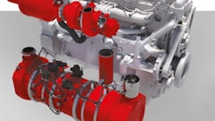
The 2010 EPA diesel emissions standards reduced emissions for on-highway engines 90% from 2004 levels, to 0.2 gram per brake horsepower hour (g/bhp-hr) for NOx and 0.01 g/bhp-hr for particulate. For off-highway engines, NOx must be reduced to 1.5 g/HP-hr, and the particulate standard is reduced to 0.01 g/HP-hr PM. The Euro 6 standards require NOx and particulate emissions for diesel on-highway heavy duty engines to be below 0.4 (g/kW-hr) and 0.01 (g/kW-hr) respectively. Substantial improvements were achieved starting in 1996 with the introduction of ultralow sulfur diesel fuel, which emits only 11 ppm of sulfur, a 97% reduction compared to the previous diesel fuel generation. Further improvements followed with the adoption of advanced combustion technology, which involves fine-tuning injection parameters such as injection pressure, injection timing, shape of injection profile, etc. Cooled exhaust gas recirculation (EGR) systems have been used since 2002 by major engine manufacturers such as Cummins, Detroit Diesel, International, Mack and Volvo to reduce NOx emissions from diesel truck engines. These systems divert from 5 to 30% of an engine’s exhaust stream through an air-to-water cooler, then back into the combustion chambers, where the cooled gases reduce peak temperatures and, thus, retard NOx formation. They have been instrumental in meeting pre-2010 standards.
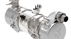
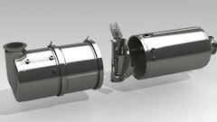
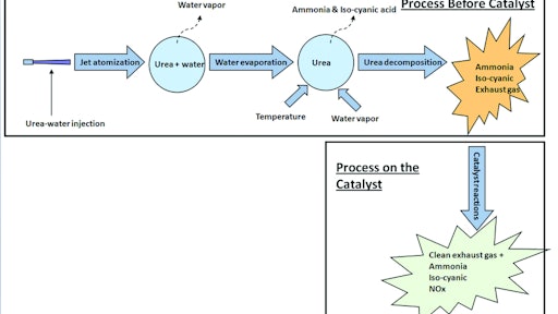
However, the new regulations have forced engine manufacturers to look beyond reducing emissions at the source and focus on treating the exhaust gases after they leave the engine. Aftertreatment techniques for NOx reduction include SCR, NOx adsorbers and lean-NOx catalysts. SCR is the most popular NOx aftertreatment technology. Here’s how it works: Aqueous urea is injected just upstream of the catalyst. Urea decomposes into ammonia and isocyanic acid. Ammonia and isocyanic acid react with NOx over the catalyst, producing nitrogen and water. SCR provides high NOx conversion efficiency and is less sensitive to sulfur. Typically, for a simple open-loop system, the conversion efficiency is 65%, which can be increased up to 95% with a sophisticated closed-loop system. Further, higher NOx conversion allows tuning the engine combustion system for better fuel consumption. Engines with SCR technology provide up to 5% better fuel economy compared to 2010 non-SCR engines.
SCR design challenges
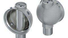
Several design challenges stand in the way of achieving the full potential of SCR technology. The most important is ensuring that a given SCR system design achieves the required level of NOx reduction over the full operating cycle of the specific engine it fits into. SCR performance needs to be evaluated over a wide range of conditions, such as traveling at 70 mph down an interstate freeway and delivering goods in stop-and-go traffic in the city. A common problem that prevents SCRs from achieving their potential is the release of unreacted ammonia, which is called ammonia slip. This can occur when excess ammonia is injected or when there is insufficient catalyst surface area. Ammonia slip can also arise from an uneven mixture of ammonia, which leads to overly high concentrations of ammonia in certain areas of the SCR along with a low concentration of ammonia in other areas. Another potential problem is urea crystallization, which can occur when excess urea injected into the process accumulates on surfaces. This problem is particularly prevalent just upstream of the injector, where there are often recirculation zones in which urea particles become entrapped. The particles can accumulate on surfaces of the SCR system, increasing back pressure and potentially reducing gas mileage and engine performance.
Engineers designing SCR systems need to develop a deep understanding of process and equipment performance at both the component and system level. Physical testing plays a critical role in the design process; however, building and testing physical prototypes is expensive and time consuming. Often, an engine with the characteristics needed to accurately test an SCR system is not available during the design process. In any case, meeting today’s tough emissions requirements — which maybe even tougher in the future — may require evaluation of hundreds or thousands of potential designs, far more than would ever be practical to build and test. The enormous complexity of the SCR process, the many different design variables, and the fact that the design process involves chemical, fluid flow, thermal transfer and structural disciplines all serve to further increase the difficulty of design optimization.
Simulation of SCR systems and components
These challenges are being addressed by a new generation of simulation tools that can be used to model the fluids, thermal, structural and chemical behaviors of SCR components and systems. These tools are based on a simulation platform that improves productivity by providing a comprehensive yet smooth workflow including:
- Bidirectional connectivity with all major CAD platforms for easy CAD data exchange, native geometry cleanup and meshing tools
- CFD and FEA solvers in the same environment, under one platform, which allows seamless data exchange and contributes greatly to FSI and thermal simulations
- Design exploration/optimization/design of experiments
Engineers can use computational fluid dynamics (CFD) technology to understand the mixing of urea with exhaust gases, its evaporation and decomposition, the ensuring chemical reactions, and the resultant thermal behavior of the exhaust gases and mechanical components. The team can apply finite element analysis (FEA) technology to model the structural behavior of components under stress and vibrations. The model can be parameterized so that the design variables can be automatically controlled by the environment that is used to automate the analysis and optimization. The analysis routine manipulates these design variables to construct a series of iterations that explore the entire design space and can be used to quickly identify the design that will best achieve specific objectives, such as meeting emissions requirements at the lowest possible cost.
A custom utility can be used to dramatically reduce the amount of time required to set up the process. Once the SCR system’s geometry is imported into the simulation environment, it takes only five to 10 minutes to provide the information necessary to perform the analysis. Another advantage of this semi-automatic process is that it provides a consistent process flow that helps to avoid mistakes. For example, urea and water are provided as the default injection species. The proportions in this example are set up as 0.675 water and 0.325 urea, but these defaults can be changed by a user to reflect his own standard practices. The panel assumes a typical diameter and orientation for the injector and, again, the user can change these to match the specific design.
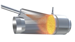
Once these inputs are entered, the software models the flow region starting upstream of the urea doser and progressing to the outlet of the catalyst. Multispecies analysis accounts for each constituent of the exhaust stream. The simulation typically begins with urea water injection into the exhaust gases. The jet interacts with high temperature gases and starts evaporating water. At higher temperatures, urea reacts with exhaust gases and decomposes into ammonia and isocyanic acid. The decomposition is modeled using a two-step reaction:
NH2—CO—NH2 g NH3 + HNCO
NH2—CO—NH2 + N20 g 2NH3 + CO2
Mixing is a critical design consideration of an SCR system, so turbulence in the flow is typically captured using a sophisticated turbulence model. Urea injection is simulated as a flow of discrete particles that are tracked in the Lagrangian (travel in time) frame. Advanced models are used to accurately simulate wall-film formation, breakup and evaporation of aqueous urea droplet particles, and decomposition into ammonia and isocyanic acid. Features such as in situ adaptive tabulation (ISAT) algorithms and chemistry agglomeration can be used to speed up the chemistry calculations.
Detailed de-NOx reactions can be modeled to predict NOx conversion ratios. In addition, the results of the simulation can be presented as graphical images and animations that enable engineers to gain a much better understanding of the proposed design than could ever be achieved with physical testing, since the breadth and quantity of information is much greater. For example, the CFD simulation predicts uniformity of flow, ammonia and isocyanic at the catalyst entry. Simulation can generate animations that plot the flow of particles through the SCR system. Thus, the engineering team can easily spot dead zones and gain an understanding of the geometrical features that are causing them. The concentration of different species can be plotted on model cross sections or surfaces, such as on the catalyst itself to help understand mixing performance. Likewise, any output variable including flow velocity and direction, temperature, pressure, and species concentration can be viewed in tabular or graphical format.
Modeling thermal stresses on SCR structures
Catalytic conversion occurs at high temperatures typically above 500K. These temperatures are applied to exhaust aftertreatment components. Changing engine load conditions lead to fluctuating exhaust gas temperatures that, in turn, produce high thermal stresses and the potential for thermal fatigue in exhaust components. Fluid structure interaction (FSI) technology can be used to apply the wall temperatures calculated by the CFD simulation as an input to FEA, which predicts the stress and deformation of the SCR structure. With sequential coupling, the fluid discipline is solved sequentially, and the results are passed as loads to the structural discipline with convergence between the individual disciplines obtained at each point in the solution. The results are passed across a dissimilar mesh interface, allowing the fluid and structural meshes to each be optimized for their applications. The robust convergence behavior of implicit coupling ensures accuracy and minimizes the engineering time needed to achieve valid simulation results.
Iterating to an optimized design
An original SCR model is typically based on an existing prototype so results can be correlated to physical testing to check accuracy. Once the model has been validated, a user can quickly evaluate the performance of a large number of iterations to optimize the design. The analyst manages parameters defined within the analysis from a project window, making it easy to investigate multiple variations of the analysis. From within the project window, a series of design points can be built up in tabular form and executed to complete a what-if study in a single operation. For example, a user can study the effect of injection parameters such the start of injection, injector orientation, etc.
The traditional approach to optimizing a product or process using computer simulation is to evaluate the effects of one design parameter at a time. The problem with this approach is that interactions between design factors and second-order effects mean that this approach is likely to result in a locally optimized design that will provide far less performance than the global optimum. The latest simulation tools incorporate the use of design of experiments (DOE) via response surface methods (RSMs) to drive the design process. DOE/RSM can be used to develop experiments that examine first-order, second-order and multiple factor effects simultaneously with relatively few simulation runs. The analyst can iterate to a globally optimized design with a far higher level of certainty — and in much less time than the traditional approach.
In summary, the ability to accurately model the performance of SCR design concepts without having to build a prototype makes it possible to evaluate many more designs in the same time frame. Add in the fact that simulation provides even more design data than physical testing, and it is possible to achieve a substantial improvement in performance. At the same time, the lower cost and shorter lead times of simulation provide faster time to market and reduced development costs.
ANSYS, Inc., Southpointe, 275 Technology Drive, Canonsburg, PA 15317 U.S.A. Ph: 724.746.3304, Email: [email protected] , Web site: http://www.ansys.com/