The market for electric vehicles is growing rapidly, including for off-highway electric vehicles (EVs). And while battery life for passenger EVs gets most of the industry hype, designing and testing long-lasting and durable batteries for the off-road vehicle sector is just as critical, and even more complex for design engineers to consider.
With off-road vehicles, the battery pack is subject to significant vibration and shock as the vehicle operates on rough ground and may carry heavy loads. Ensuring the battery pack can withstand off-road vehicle vibrations requires additional testing. Not only must the test protocol include performance and safety testing, but it must also include vibration and shock testing.
The key component in any type of EV is the battery pack, which consists of numerous individual battery cells connected in series and parallel configurations. As the EV market grows, the demand for batteries grows. The U.S. Department of Energy (energy.gov) forecasts that by 2030, EV battery manufacturing in North America alone will produce annually 10 million to 13 million batteries.
Each EV battery requires testing for performance and safety. Today’s technology employs Lithium-ion (Li-ion) batteries, which have high energy density with the tradeoff that Lithium is a highly reactive metal. A manufacturing defect in construction of a battery cell or a poor (high resistance) connection between battery cells can result in the build-up of heat and thermal runaway. The high temperature can destroy battery cells and cause severe damage to a vehicle.
Challenges With Increasing Production Volume & Enhanced Battery Capacity
The need to both increase production throughput and develop test systems that adapt to the evolution of higher-capacity battery packs are the two other major challenges that the design and test engineer faces. Volume growth demands more manufacturing test productivity in the least amount of space.
Battery manufacturers are developing EV batteries with higher amp-hour capacities to increase driving distance for consumer and commercial vehicles and to increase working hours for industrial vehicles. Furthermore, EV battery manufacturers are designing higher-voltage battery packs. For a specific power requirement, a higher battery pack voltage enables the load to draw less current. This allows the EV designers to use smaller gauge wire in cable assemblies, which reduces weight and power loss in the cables. As a result, less heat builds up in the cable assemblies. EV battery pack voltages are transitioning from 450 V up to around 800 V.
Essential Battery Pack Performance & Safety Tests
The tests that battery manufacturers need to perform include:
- DC internal resistance — Determining the internal resistance is a measure of the battery’s state of health (SOH) and the capacity of the battery. A high internal resistance in excess of the battery pack specification is indicative of a problem with the battery pack.
- Insulation resistance — Measuring insulation resistance helps to identify internal insulation defects in the battery pack. An insulation resistance lower than the specification results in higher leakage current, reducing battery efficiency and posing safety concerns.
- Battery cycling — Conducting charge and discharge cycles to ensure the battery conforms to its characteristic voltage-time curve during discharge into a fixed load and the battery charges within a specified time interval. Battery cycling also provides an estimate of cycle life, the number of charge and discharge cycles a battery can have before capacity is significantly degraded.
- Pulse testing — Short duration, high current pulses simulate rapid acceleration and regenerative braking conditions that require the battery to deliver or absorb high currents for short time intervals. Pulse testing determines how well the battery can dissipate heat during high power demand and absorption conditions. Good thermal design protects the battery from damage during overheating conditions. Pulse testing also helps evaluate the state of charge (SOC), which is important for predicting driving range or usage time.
- Drive cycle simulation — Simulating varying loads on the battery, such as driving on hilly terrain, verifies the battery meets its driving distance specifications. Standard drive simulation tests such as Federal Test Procedure (FTP-75) exist to compare battery performance among battery manufacturers and vehicle performance among the EV manufacturers.
- Vibration and shock testing — These tests are particularly important for assuring the battery can perform reliably in off-road vehicles. This testing is performed during battery pack research and development and is a quality control test performed on a statistically significant number of production battery packs. The test involves subjecting the battery to various vibration modes and intensities to check for mechanical weaknesses exacerbated by vibration. Also, a drop test simulates the mechanical shock a battery in an off-road vehicle will encounter.
Testing is essential for the high-cost EV battery packs needed to power both on- and off-road vehicles. Maximizing throughput and minimizing the required test footprint are also critical for cost-efficient manufacturing.
Instrumentation Solutions
Careful review of instrumentation can yield solutions to overcome the challenges of battery testing. Figure 1 illustrates an example turnkey battery test system that includes power instrumentation, measurement instrumentation, a PC with data acquisition and control software for performing tests over a range of temperatures. The following sections offer recommendations for DC power instrument capability to enable thorough battery testing.
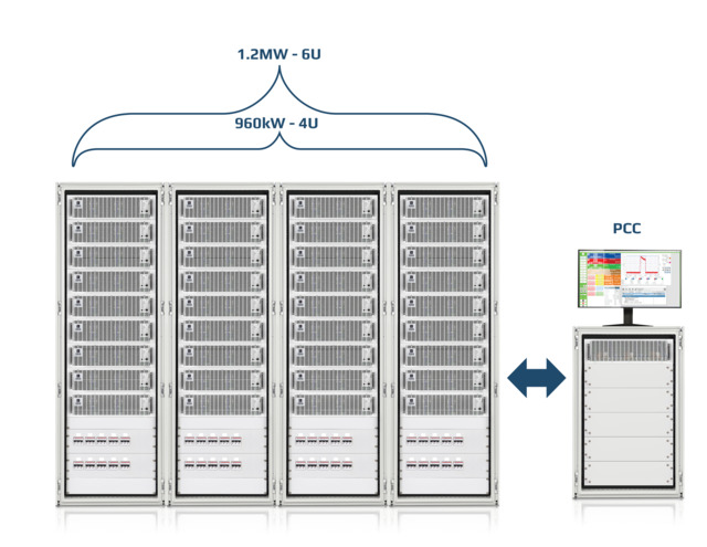 Figure 1. A battery test system that includes power instrumentation, measurement instrumentation, PC with data acquisition and control software.EA Elektro-Automatik
Combining source and load functionality
To discharge and charge the battery pack, the functions required are an electronic load and a power supply. The test engineer can save production space and capital costs by selecting a bidirectional power supply. Bidirectional power supplies can both source and sink DC power. Use of a bidirectional power supply simplifies system wiring by eliminating the need to connect two instruments by switching to the battery pack. Thus, one instrument can combine both the sourcing function and the loading function to save space, costs, and system wiring complexity.
Maximizing flexibility of the bidirectional power supply
Testing a battery pack can require discharging it at a constant power over a range of voltages. A DC power supply with a conventional rectangular output characteristic can only deliver maximum power at the maximum voltage and maximum current point. A power supply with an autoranging output characteristic can output maximum power from its maximum rated voltage down to a percentage of its rated voltage. Some supplies can output maximum power down to 1/3 of the maximum rated voltage. Figure 2 shows an I-V plot of an autoranging supply’s output (in red) compared with an equivalently powered supply having a rectangular output (blue rectangle). The wide current range of the autoranging supply allows full power testing of 4.2 V battery cells, modules, and battery packs with a single instrument.
Note that the power of the rectangular output supply would have to be tripled to 15 kW to enable delivery of 5 kW at various voltage levels. The autoranging supply saves cost and rack space compared with a rectangular output supply.
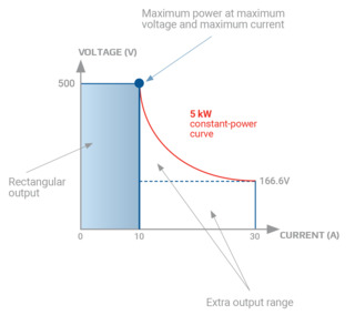 Figure 2. I-V plots of a 5 kW autoranging supply (red curve) compared with a rectangular output supply (blue rectangle)EA Elektro-Automatik
Creating load profiles
Simulating real-world load conditions on a battery requires a test configuration with a programmable load and an arbitrary waveform generator. Some bidirectional power supplies can create a complex load profile with a built-in arbitrary waveform function generator. Again, a single instrument saves the cost and complexity of adding an extra instrument to the test system. The built-in function generator allows the bidirectional power supply to simulate a battery in source mode and to simulate drive conditions in load mode.
Saving energy
When investigating bidirectional power supplies for EV battery tests, consider the amount of power absorbed when the supply is acting as a load for the battery pack. Some supplies have circuitry that returns the absorbed power to the AC lines. These regenerative power supplies can return over 96% of absorbed power to the grid. For high-power batteries, the utility savings can be significant.
Optimizing pulse testing
Accurate assessment of pulse testing data requires that the battery responds to square wave pulse loads that simulate rapid acceleration or accept a charge pulse from regenerative braking. Pulses with highly rounded edges produce waveforms that do not substantially stress the battery and can yield incorrect test results. Creating sharp edge pulses requires a power supply with a fast slew rate, the speed at which an output (or input) changes from its current level to the programmed pulse peak level.
Avoiding missed information
Vibration testing for off-road EVs is one example where fast data acquisition is essential. If the vibration of the battery pack causes an intermittent broken connection that might last only a millisecond, a slow data acquisition rate may not capture the event. The battery could pass production testing and cause a premature failure in an off-road vehicle.
Saving space
If testing high-power battery packs is necessary, the power instrumentation can consume substantial space. Power instrumentation that uses SiC semiconductor technology offers high-density instrumentation and minimizes consumption of precious production floor space. Figure 3 shows an example of a high-power test rack.
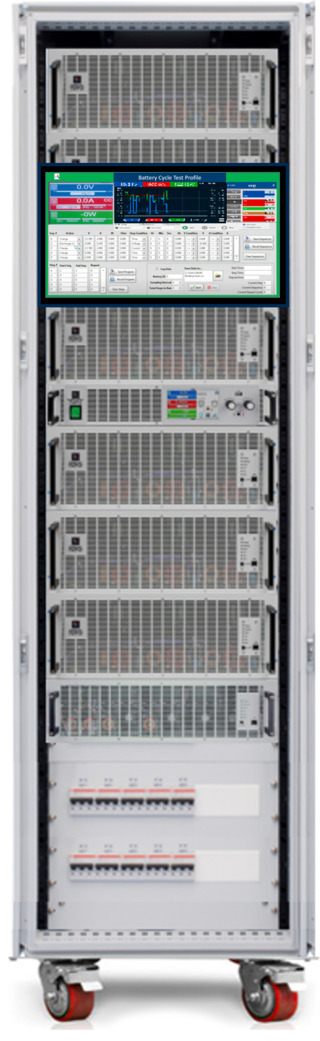 Figure 3. 300 kW system from packaged in a single 19 in test rackEA Elektro-Automatik
Multiple Options for Battery Test Systems
Fortunately, high-performance instrumentation exists to address the requirements for battery test. The test engineer has the option of a turnkey system, such as the system shown in Figure 1, which maximizes throughput and data analysis. Alternatively, Individual instruments with multiple outputs contribute to throughput improvements and small footprints as illustrated in Figure 3. The test engineer can simplify test systems and reduce instrument requirements by using bidirectional power supplies. Furthermore, the test engineer can combine a third instrument into the bidirectional power supply. That instrument is an arbitrary waveform function generator for battery and load profile simulation. Finally, regenerative energy recovery and high-power density instrumentation allow assembly of cost-effective, space-saving battery test systems.
Russ Gaubatz is a senior applications engineer, SME, at EA Elektro-Automatik.