Tier 4 engines continue to change the game in the world of system optimization with their direct impact on the need for anti-cavitation valves. Quickly decelerating loads and engines are allowing design engineers to save time and money by removing the anti-cavitation valve from the system. Proper analysis can help you determine whether or not an anti-cavitation valve is necessary in your application.
Anti-cavitation valves were designed and introduced into circuits in the early years of hydraulics to protect the shaft seals. In those days, the two primary shaft seal designs included mechanical seals and leather "packings." Despite their innovative design, both seals proved to be problematic when attempting to seal against negative pressures and contamination.
“The problem with these leather 'packings' was they lacked the spring mechanism necessary to prevent the contamination during pressure changes,” says Alfred Permann, Engineering Manager, Turolla OpenCircuitGear (OCG; company information, 10472769), a member of the Sauer-Danfoss group, Ames, IA.
Nowadays, most applications have elastomeric shaft seals that reduce the risk for contamination caused by directional pressure changes. However, although elastomeric seals perform better than the previous designs, experience shows that nearly 80% of damage to hydraulic components today is still due to contamination migrating past the shaft seal.
Seal isolation: What happens in there?
Typically, in most hydraulic motors, the seal area is isolated from the normal fluid path with a special passage specifically dedicated to venting the shaft seal cavity directly back to the reservoir. In these products, the shaft seal will not be exposed to the actual pressure at the supply or return ports.
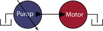
In axial piston pumps and motors, the high pressure fluid cavities are still isolated, however, the internal components are affected by the magnitude and direction of the delta pressure between the supply and return pressures and the case pressure. “When either the supply or return pressure falls below case pressure, there is a reversal in the direction of the differential force across the pistons,” says Jeffrey Hansell, Staff Engineer, Sauer-Danfoss (company information, 10056055). “Over time, the internal components can become damaged, especially when the motor is operating at high speed.”
Although most open circuit applications don’t have enough back or return line pressure to result in accumulated cavitation damage, closed circuit applications with high inertial loads may produce sufficient energy to cause the pitting damage that is commonly associated with cavitation.
The minimum pressure in the supply cavity of the motor will be determined by the rate of change of the supply flow from the pump (or any external source), and the rate of change of flow required by the motors as they both decelerate.
Determining your needs: The analysis procedure
In the analysis, the initial value of the load speed is taken and decelerated down to 1 rpm in 200 intervals. For each interval there is a change in speed which is equal to the acceleration rate multiplied by a time interval. Likewise, the acceleration rate is equal to the applied drag torque divided by the effective load inertia. Consequently, if the combined drag torque and the effective inertia are known, one can solve for the time interval for each increment of speed change.
At that point, the time intervals can be accumulated to find the total time it takes for the load/motor assembly to decelerate to 1 rpm, or essentially stopped.
Inputs to the analysis include:
- Rated load power and speed
- Actual load speed, i.e., the speed at the initiation of the event
- The Mass Moment of Inertia of the load/motor assembly
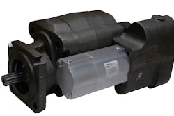
- The displacement of the hydraulic motor
- The mechanical drag torque of the hydraulic motor — This data is sourced from the manufacturer and is plotted against motor speed; the “best fit” trend line for the data is calculated to correlate the drag torque to the actual speed for that interval of the analysis.
- The engine speed at the initiation of the event
- The pump drive ratio
- The displacement of the pump
- The time interval for the deceleration of the prime mover
- The maximum pressure drop through the hose and fittings — The maximum return flow to reservoir is determined by the maximum load speed and the motor displacement. Use this value and various available reference books to calculate the pressure drop across the return hose and fittings.
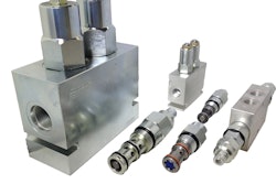
- The pressure drop through the anti-cavitation check valve — Determine the cracking pressure and the valve’s flow coefficient.
- The pressure drop through the back pressure valve on the motor’s return line — Determine the cracking pressure and the valve’s flow coefficient.
A spreadsheet is a useful tool to perform this analysis and to display the results. An example portion of the final spreadsheet for this analysis is shown below.
[insert "speed" and "system fan drive" photos here]
The motor back pressure is calculated based on the actual motor flow minus the anti-cavitation valve flow for the respective fan speed. The required anti-cavitation valve flow rate is calculated as the difference between the actual pump flow and the required motor flow. The value is defined as zero until the pump flow rate falls below the required motor flow rate.
Delta pressure across the anti-cavitation check valve is determined by the cracking pressure of the valve and the valve’s flow coefficient. The cracking pressure for the valve is found in the supplier’s technical literature. The valve’s flow coefficient is calculated by dividing the maximum flow rate by the square root of the valve’s maximum delta pressure.
In this analysis, it was determined that the anti-cavitation valve would open when the motor was at 400 rpm. At this speed, it is unlikely that the motor would sustain any damage; but, there may be an intermittent, audible sound during the final deceleration of the motor that could be interpreted as undesirable by the customer. In every instance, it is the customer’s perception of quality that determines whether an anti-cavitation valve is needed.
System solutions
In an ideal system, if the motor can decelerate faster than the engine, then conditions leading to reduced pressure and damage in the supply port of the motor cannot occur. This may seem obvious, but it helps us identify which parameters can be changed in order to prevent cavitation, or damage to the hydraulic motor.
Typical parameters may include adding back pressure to the return line of the motor to ensure that it can decelerate faster than the engine. For this to be successful, the supply port of the motor must not cavitate and back pressure should be minimized at the motor case return port. Throckmorton suggests choosing an engine that has higher inertia so that it takes longer to decelerate. Increase the flow capacity of the anti-cavitation check valve to minimize the cracking pressure of the valve, and choose a load with lower mass moment of inertia in order to achieve desired motor deceleration speeds.
As engine systems and overall vehicle performance demands continue to evolve, components and systems should always be evaluated and reevaluated to determine their continued relevance and contribution to achieving system efficiency and vehicle improvement.