Electro-hydraulic controls are increasingly replacing hydraulic controls in commercial vehicle applications. New controls, with better ergonomics, incorporating multiple functions, are required to improve operator and machine efficiency and ensure safe operation of the vehicles.
The engineering team at elobau has built on their experience of many years designing armrests and controls for the commercial vehicle industry (in particular agricultural tractors, construction equipment and forklift trucks) to develop a new concept of joystick handles which is addressing most of the new requirements driven by the change to EH controls.
This new concept is the result of years of industry experience in mechanical design, machine safety and contact-less sensing technology. It combines outstanding ergonomics, innovative modular design allowing a wide variety of controls configuration around a basic concept, and the unique integration of two features inside the handle, a capacitive presence sensor and a CAN controller, making it a highly integrated control solution.
Electrohydraulic control trends
Nowadays, cab designers have to fulfill the need for increasing functionalities controlled directly at the tips of the operator’s fingers, which leads to more and more complex multifunctional grips or handles. This complexity can be confusing for the operator if the ergonomics and visual appearance of the controls do not allow for instant identification of the functions, specifically during night time operation of the equipment, and particularly if some of the controls are not activated on a frequent basis by the operator.
The evolution from solenoid valves controlled by simple switches, to proportional EH controllers requires the availability of multiple proportional controls in the joystick handles, with outputs compatible with EH controllers inputs, instead of simple push button switches.
Increased operator comfort is also required in order to achieve higher productivity with less fatigue, and therefore a safe operation of the equipments over extended periods of time, thus the requirement for state-of- the-art handle ergonomics has become increasingly present in new cab designs. Many applications also require to have controls with ergonomic designs specific for left and right hand grips, particularly in seat mounted armrests.
The aesthetics of the handles becomes more and more important in most of modern cabin designs, particularly for high end agricultural tractors, leading to automotive-like finish of the controls such as chrome or soft pad materials. Symbol graphics have to blend with the aesthetics of the handles, and at the same time must be resistant to abrasion and environmental conditions, in order to be durable during the lifetime of the vehicle.
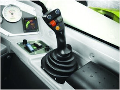
Figure 1. Joystick handle in modern telehandler cab
There is also a trend to improve lifetime and uninterrupted service on the field, as many equipments are now leased with full service contracts rather than owned. Therefore a more than ever important criteria for the new controls is reliability, and the capability to perform their service over a long period of time in the toughest possible environments. Open cab configurations, with extreme temperature variations, exposure to water, dust and various chemical agents, and safe operation in environments generating significant levels of electromagnetic perturbations inside and outside of the equipment have become common requirements for joystick handles.
Integrated CAN controller
Most available joystick controllers on the market have their CAN electronics located inside the base of the joystick, and therefore many wires are necessary to link the multiple handle controls to the CAN electronics. One of the unique features of this new generation of handles is the integration of a high performance CAN controller inside the grip itself. This is the first standard series handle of this kind developed for commercial vehicle applications.
One of the benefits is the possibility to limit the number of wires connected to controls and LED’s incorporated inside the handle, thus avoiding having a bundle of moving wires between the handle and the joystick base. This can also save time and money in the production process of the equipment, and allows to expand the number of controls and LED’s that can be incorporated inside the handle. It also allows to easily implement the handle on a conventional hydraulic joystick base.
In configurations without the CAN option, the maximum number of wires would be limited to 14, therefore also limiting the number of functions that can be incorporated inside the handle.
Another advantage of the grip-integrated CAN module is the possibility to reduce the required space envelope inside the armrest´s front end, where collisions with the ergonomic knee zone have to be avoided.
Figure 2. Location of the CAN controller (and capacitive sensor) inside the handle shell
With the CAN controller, the number of wires coming out of the controller is limited to four: UB, Ground, CAN-H and CAN-L. (If the CAN module controls the joystick base, then additional wires will be routed from the base to the handle).
The interface uses CAN Specification 2.0B, as specified in ISO11898, and supports the standard protocols CANopen and SAE J1939.
The default Baud rate is 250 kBit/s and can be configured from 50 up to 1,000 kBit/s in the CANopen version.
|
Baudrate kBit/s |
Default |
Min. |
Max. |
Values |
|
CANopen |
250 |
50 |
1000 |
50, 125, 250, 500, 800, 1000 |
|
J1939 |
250 |
N.A |
N.A |
N.A |
Figure 3. Standard CAN Controller configuration
The CANopen version provides a Node-ID that can be selected between 1 and 127 (default ID is 17). The cycle time can be configured between 1 and 65535 ms (default cycle time is 100 ms).
The standard CAN controller is designed to accept up to 10 analog inputs, 11 binary inputs, and 16 binary outputs.
Analog inputs are in general used for the main joystick X and Y axis signals, or auxiliary thumbwheel(s), or analog push button controls. Up to 2 analog inputs are necessary for each joystick axis or thumbwheel controller if signal redundancy is required in the application. The input voltage range is 0 to 5V DC.
Binary inputs are used for push-button switches and for the capacitive presence sensor input.
Binary outputs are used to command LED’s, which are for example implemented for backlights or activation lights on the handle and on the individual controls, or other function LED’s installed in the handle.
The standard controller allows to implement several possible configurations on the handle, the maximum configuration being:
- 8 push-button switches or 5 push-button switches and 2 thumbwheel controllers on the face plate
- 2 push-button switches or 1 push-button switch and 1 thumbwheel on the rear plate
- Each push-button switch can have 1 LED for backlight and 1 LED for activation
- Each thumbwheel on the faceplate can have multiple LED’s (see paragraph 5 – Modularity/Versatility).
The CAN controller accepts a supply voltage from 9 to 36V DC, with reverse polarity protection up to -36V DC. The maximum current consumption is 500 mA, with the maximum configuration including LED’s (120 mA without LED’s).
The CAN hardware controller is designed to withstand EMC environment present in vehicles according to the following standards:
- DIN EN 550252
- DIN ISO 11452-5
- DIN ISO 7637-2
It was also tested to withstand ESD according to ISO/TR 10605 with contact discharge up to ±8kV and air discharge up to ±15kV.
Capacitive presence detection
An optional capacitive sensor is designed to be built inside the joystick handle. The sensor will activate an output as soon as an operator’s hand touches an area located on the outer side of the handle, thus allowing for a validation of operator presence, which can be used to validate the activation of specific machine functions. The default sensibility setting detects a light hand touch, and therefore the sensor can be used for redundant presence detection, and not as a primary safety function.
Figure 4. Capacitive presence sensor area inside the handle
Thin isolation or working gloves will activate the capacitive sensor with default settings, special gloves, such as thick cold storage isolation gloves used by forklift truck drivers would require a special programming of the activation software, to increase the sensitivity of the capacitive sensor. If such settings are required, a compromise would have to be found to adjust the capacitive sensor to work with both bare hands and thick gloves, and the detection software will have to be modified accordingly.
The sensor principle is as follows: Like in a capacitor, two electrical conductive electrodes have a defined capacitance. This capacitance is affected by the dimension of the electrodes, the distance and the permittivity. When a conducting object approaches these electrodes (e.g. a finger or the operator’s hand) there will be a parallel capacitance present between the object and the capacitive sensor. The original capacitance will change and this will be identified by the sensor. Parameters like hysteresis, sensibility and distance of switching on and off can be adjusted through the controller software.
Figure 5. Capacitive presence sensor diagram
The sensor works with a 5V DC supply voltage and delivers up to 150 mA through an open collector output.
Versatility and modularity
The 36xG Series of handles has two basic versions, right hand (361G) and left hand (362G), each version provides as many as nine different functions, thanks to its modular, interchangeable face and rear plates, associated with a modular PCB concept.
Figure 6. Handle (face, side and rear view)
Up to three analogue thumbwheels combined with six push buttons switches or two analogue thumbwheels combined with seven push button switches can be mounted in each of the versions (left and right), in addition to the optional capacitive presence sensor.
Figure 7. Interchangeable face and rear plates
Moreover, many other configurations are possible, including an auxiliary four position analog control installed at the top of the handle.
Figure 8. Face plate of handle with modular PCB
The push-buttons can be either binary switches based on Reed technology, and available with or without backlight and activation light, or analog linear Hall effect push buttons with 0.5 to 4.5V output. The patented Nano push-button switch mounts and connects directly onto the PCB.
Figure 9. Nano push-button switch directly mounted on handle’s PCB
The thumbwheel controls use Hall effect technology and are available with single output or redundant output signals, with optional backlit and/or activation LED’s.
The thumbwheels are available with 0.5 to 4,5V single output, or dual redundant output signals.
Figure 10. Redundant output voltage on thumbwheel
This provides a wide range of possibilities to combine the required controls, in order to operate a wide spectrum of various vehicles or equipments, with the appropriate back lit illumination to make the controls easily identifiable by the operators, particularly during night shift operation. In addition, visual feedback information about the specific status of these controls can be provided to the operator.
Figure 11. Hall effect thumbwheel with three LEDs of different colors for three separate positions
The modular concept will be developed and extended to a wider range of standard handles of different shapes and sizes, as well as customer specific designs.
Ergonomic features
Designers have taken into account various ergonomics considerations very early in the process. for both, left hand and right hand versions of the handle.
The handle shaft bends to front and inner direction to allow ergonomically correct hand and arm joint angles and positions, when the joystick grip is incorporated in seat mounted armrests or similar configurations.
The smooth-shaped integrated hand keeps individual operator’s hands in the right ergonomic position to reach controls integrated in the handle, and provides arm relaxation even in configurations without an additional arm support.
The tilted handle head allows symmetrical and fatigue-less thumb actuation of auxiliary controls (push-buttons, thumbwheels, mini-joysticks) located on the large actuation board.
Besides that, the eye-alignment provides the best possible view of the face plate by the operator, which allows instant identification of all controls.
Figure 12. Handle ergonomics and design studies
A recessed area was designed to provide perfect grip when the thumb is not used during the actuation of the joystick on which the handle is mounted, keeping the hand in the best possible position and limiting accidental actuation of auxiliary controls.
Figure 13. Backlight illumination and activation LED’s on multifunctional handle.
Design and functions
In order to make this new concept of handle available for mounting on as many existing joysticks as possible, a wide range of mechanical interfaces and rubber boots have been designed as standard accessories.
Figure 14. Interchangeable shaft interfaces and rubber boots
The handle can therefore be mounted to a wide variety of mechanical, electro-mechanical, hydraulic or electronic joysticks available on the market.
To enable best identification by the operator, apart from various standard icons, individually designed symbols can be realized on the push-button actuator caps, protected by the backside printed and therefore abrasive-resistant technology. The available symbol area is a circular surface with 10mm diameter.
Figure 15. Push-button switch with abrasion resistant symbol plate.
The color differentiation of the handle shells is a convenient feature for applications with multiple functions in the operator’s cab, and allows the cab designer to implement maximum differentiation from competitors products at limited costs.
Figure 16. Handles are available in various colors
The stiffness-optimized shell concept withstands actuation forces up to 1000 N, which surpasses most heavy duty vehicle specifications and joystick base capabilities.
Behind that, the parallel low-weight-strategy limits negative inertia effects under acceleration conditions.
The materials of the reinforced handle shells resist toughest environments with operating temperatures from -25 to 85 C and storage down to -40 C.
An extensive test program, based on the specifications established by market leaders in the vehicle industry, was successfully conducted on the handle. It includes EMC, shock, vibration, exposure to UV, humidity dust, water, and chemical resistance tests.
SUMMARY/CONCLUSION
This new generation of multifunctional handles opens new perspectives in the field of EH controls by combining improved ergonomics, unique safety features, and modern CAN electronics. Thanks to a well thought-out design, taking into account a wide range of requirements requested by operators and cab designers, the modularity of the handle design allows to obtain a wide spectrum of features, in order to provide a unique joystick controller for any specific application or vehicle.
Ergonomics, aesthetics, symbols, auxiliary controls, electronic circuit, signal interface, and other functionalities, can be easily defined and built without the need to go through the costly process or generating a new design, with new tools and new components for every new application.
Moreover, with the availability of mechanical interfaces and various rubber boot adapters, the handle can be applied to new designs, as well as retrofit to improve existing designs.
Typical applications include vehicle controls for a wide variety of machines such as excavators, wheel and backhoe loaders, dozers, skid steer loaders, and other construction, mining and forestry vehicles, as well as agricultural tractors and combines, forklift trucks and other material handling equipment.
Authors are employed by elobau sensor technology in Leutkrirch, Germany and Gurnee, Illinois – Contact information is available at www.elobau.com