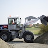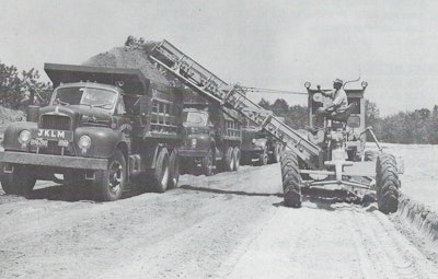
The original elevating graders (EGAs) were drawn by stock, and tractor-drawn elevating graders were used into the 1940s before being rendered obsolete by advances in belt loader and scraper technology. However, unlike many other obsolete machines, the idea of the EGA experienced a revival in the 1950s and early 1960s as the concept was adapted to motor graders, which, for the sake of convenience, will be called parents.
The majority of EGAs were mounted to the motor grader’s frame in place of the circle and blade, and were designed to be more or less easily detached and reinstalled as needed. Jebco estimated 40 hours for initial installation, and eight for subsequent removal. In contrast, the Austin-Western Plainsman was pulled behind the motor grader, and the Rivinius R300 Multi-Purpose Loader was essentially a force-feed loader pulled by a motor grader.
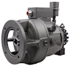
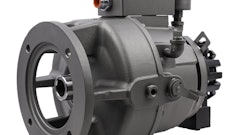
Most EGAs could be used for a wide range of tasks, including excavation, embankment placement from roadside ditches, stockpile aeration, windrow removal, construction of citrus orchard planting mounds, and stripping of broken asphalt pavement. Most were powered from the parent’s PTO, and side-discharge EGAs required right-angle linkages to convey the power from the rear to the middle of the parent (Figure 1). Cutting discs were most often 30 inches in diameter, with larger parents getting 32- or 36-in. discs, and an EGA’s maximum digging depth was typically the diameter of the disc.
The most common belt width was 36-in. wide, smooth and on flat rollers. Jebco used a troughed belt, giving up to 30% more carrying capacity while preventing load slippage and keeping the load centered on the belt, and optional cleated or ribbed belts prevented material rollback.
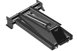
The belt was mounted in a carrier frame, from 16 to 30 ft long for side-discharge EGAs, which could be folded for transport and storage so that the upper section was vertical. Larger parents could handle larger discs and longer carriers, increasing discharge height without increasing the conveyor angle for the most efficient loading. Faster belt speed than the norm of 450 ft per minute helped as well, so long as it didn’t cause rollback.
As with all other earthmoving machinery, the output varies with ground and terrain conditions. Of the known manufacturers, L-W and Jebco provided the most comprehensive figures for estimating an EGA’s output. The specifics vary from publication to publication, but a good example was given for the 1956 model offered for Cat No. 12 and Adams/L-W 550 and 660 parents. Equipped with a 22-ft carrier set to a 10-foot discharge height and with the parent in first gear, it could cast 700 to 1500 cubic yards or load 400 to 800 cubic yards per hour in good ground conditions.
Thomas Berry, Archivist and Editor, Historical Construction Equipment Association
The Historical Construction Equipment Association (HCEA) is a 501(c )3 non-profit organization dedicated to preserving the history of the construction, dredging and surface mining equipment industries. With over 3,500 members in a dozen countries, our activities include operation of National Construction Equipment Museum and archives in Bowling Green, Ohio; publication of a quarterly magazine, Equipment Echoes, from which this text is adapted, and hosting an annual working exhibition of restored construction equipment. Individual annual memberships are $45.00 within the USA and Canada, and $65.00 US elsewhere. We seek to develop relationships in the equipment manufacturing industry, and we offer a college scholarship for engineering students. Information is available at www.hcea.net, or by calling 419-352-5616 or e-mailing [email protected].

