To be competitive in today's volatile energy market, mineral developers continuously seek out innovative technologies that reduce production costs and increase profitability. Highwall mining, a system that extracts coal reserves lying beyond the reach of conventional surface mining operations, is a profitable method of coal extraction. A remotely controlled continuous miner extracts the coal and conveys it through augers or chain conveyors to the outside for stockpiling and transporting. The result is substantially less capital cost and reduced lead time.
Located in Beckley, WV, in the heart of the Appalachian coal fields, for the past 10 years Terex SHM (formerly Superior Highwall Miners) has manufactured machinery for many of the world's most successful and productive highwall mining operators. SHM works with mine operators to evaluate the coal seam, estimate production costs and, later, train personnel to operate and maintain its highwall miner.
SHM had determined that the string pot encoders, pressure switches and infrared switches used in its machines were less efficient and more costly than customers wanted. After exploring available solutions, SHM replaced these parts with magnetostrictive sensing technology.
The mining machine
The Superior highwall mining system is a self-contained, productive, cost-efficient coal mining machine. The system is operated and maintained on the surface. At no time does any crew member go underground. Like an auger, the highwall miner (HWM) works in front of a highwall. The HWM mines parallel entries, rectangular and up to 1,000 ft. deep. SHM is the first practical highwall mining system that can mine parallel entries to predetermined depths.
The machine is generally operated from a rock "bench" that is created by the removal of overburden and coal by way of contour surface mining. A minimum bench width of 42 ft. is required, with 55 ft. or more being ideal.
A typical cycle includes sumping (pushing forward) and shearing (raising or lowering the cutterhead boom to cut the entire height of the coal seam). As the cutting cycle continues, the cutterhead is progressively pushed into the coal seam for 20 ft. Then, the pushbeam transfer mechanism (PTM) inserts a 20-ft. long rectangular pushbeam into the center section of the machine between the powerhead and the cutterhead.
The configuration of the HWM is such that it is capable of mining coal seams ranging from 30 in. to 16 ft. in thickness and to depths of up to 1,000 ft. Mining this height range is accomplished through the HWM's interchangeable cutterhead modules.
When preparing to mine, the HWM, which travels on four hydraulically powered tracks, is aligned perpendicular to the exposed coal face.
The coal is cut by an electric cutterhead module attached to the powerhead assembly in the center of the machine. Here, two hydraulically powered sump cylinders, each with a 20 ft. stroke, push the powerhead forward as they provide up to 380,000 lbs. of force. Cutterhead modules are available with 24- to 44-in. dia. drums. The bits rotate, breaking the coal out of the seam. As the coal falls, it is gathered in a pan that uses two mechanical loading arms to assist in gathering the coal and propel it to the rear of the pan where it is picked up by a chain conveyor.
Near the mid-point of the cutterhead, the chain conveyor loads the coal into a pair of 18 in. dia. horizontal augers that transport the coal through the remainder of the cutterhead. Horizontal augers are located inside of the powerhead, and each is powered by 400 hp. water-cooled electric motors.
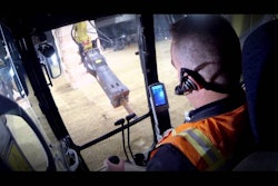
An operator runs a small front-end loader to handle the pushbeams, either by loading them onto the PTM during the mining process, or removing them during retraction and placing them in storage.
Inside the full length of the pushbeam is a pair of 18-in. dia. augers that are coupled at the rear to the powerhead and at the front to the cutterhead when the powerhead is moved forward. The mining cycle continues for an additional 20 ft. with the powerhead pushing the most recently inserted pushbeam, while the cutterhead alternately sumps and shears as it advances into the coal seam. At 20-ft. intervals a new pushbeam is inserted and mining continues to its maximum penetration.
Coal is transported from the cutterhead and discharged into the conveyor to be stockpiled. At maximum penetration, the process is reversed as the powerhead is retracted, pulling the string of pushbeams and cutterhead out of the hole.
The SHM mining process leaves a series of rectangular shaped holes up to 11 feet, 6 in. wide and as high as the coal seam up to 1,000 ft. deep.
A sensor solution
Throughout the equipment's original design, externally mounted pressure switches, string potentiometers (string pots) and infrared switches were providing feedback on position, but were often less than accurate due to the harsh operating conditions.
"Our engineers did some research, including interviewing customers that were using MTS Sensors' Temposonics technology in cylinders, and they seemed to be the best option," says Stewart Myers, director of engineering, SHM. "It allowed us to do away with expensive string pots, cable encoders and switches, and the sensors are a better choice because they can be embedded inside the cylinders, making them more reliable and longer-lasting."
The shear cylinder, for example, had originally utilized an externally mounted sensor, but the high shock and vibration of the mining environment caused dust and water to seep into the sensor and affect the performance. By replacing the external sensor with the embedded MH sensor, maintenance issues were virtually eliminated.
The sump cylinder strokes 22.5 ft. and was using a cable encoder to indicate position. As it was repeatedly pulled across the length of the stroke, the cable was at risk for damage from water, dust and kinks, resulting in much downtime for repair. The operators were changing the cable encoders at least once or twice a month.
The steering, traverse and PTM cylinders were compromised due to the use of string pots. Embedded sensors were reliable in the same conditions.
The base frame latching and locking cylinders were detected with pressure switches. The MH sensor allowed SHM to embed technology that would provide positive feedback indicating where that cylinder was at any point in time. With the pressure switch, operators were always guessing — the cylinder might be constrained in such a way that there was pressure on it, trying to force it down, but in reality it was still in the up position.
The powerhead latching cylinder was using infrared switches, but over time dust would collect on the lens, creating a nuisance for the operators who would have to shut down the equipment to clean off the lens. By replacing the infrared switches with embedded MH sensors, downtime was mitigated.
"Switching to MTS magnetostrictive sensors may have reduced our cost," says Myers, "but I know it's saved our customers money, especially in downtime. Downtime on these machines is huge — revenues can be in the tens of thousands of dollars per hour in these machines, so if they go down, it's costly."
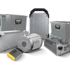
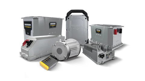
MTS' RH series and MH series sensors replaced parts in nine different cylinders in the SHM equipment. MTS' sensors utilize magnetostrictive technology for accurate and reliable results in linear position sensing. In a magnetostrictive sensor, a sonic strain pulse is induced in a specially designed waveguide by the momentary interaction of two magnetic fields. One field comes from a movable permanent magnet, which passes along the outside of the sensor tube, the other field comes from a current pulse or interrogation pulse applied along the waveguide. The position of the magnet is determined with high precision by measuring the elapsed time between the application of the interrogation pulse and the arrival of the resulting strain pulse. Consequently, accurate non-contact position or liquid-level sensing is achieved with absolutely no wear to the sensing components.
The MH sensor, which on the SHM miner is used in the shear, steering, base frame latching, base frame locking, and powerhead latching cylinders, consists of a redesigned sensor head with rugged housing and built-in electronics, a pressure-proof sensor pipe that protects the internal sensing element, and a position magnet. Along with high shock and vibration ratings, the sensor has 200v/m EMI protection. The MH sensor provides a measuring range of 2 to 78 in., doubling the available stroke length, while maintaining high levels of accuracy and repeatability.
The RH sensor used in the sump, PTM lift and PTM traverse cylinders, features position sensing resolution as low as 1 micron (0.00004 in). The resolution is factory or field-adjustable.
The R-Series sensor, having current or voltage analog outputs, is used in the sump, PTM lift and PTM traverse cylinders in the HWM. This sensor has options for programmable dual position and/or velocity channels with a maximum velocity range of up to 10 m/sec. (400 in/sec.).
Brian Cox is the technical marketing manager, Mobile Hydraulics, for MTS Sensors, Cary, NC.