Engineering has come a long way since the days of a single engineer designing and prototyping a system. Now entire teams of engineers work together on a single design, with one group having responsibility for the mechanical portion, another group the hydraulics, and yet another focusing on the engine.
In order for a cohesive design to come together, these independent groups need a way to communicate their ideas to one another, as well as ensure all of the systems will work together. This is where model-based design software such as that from MathWorks, Natick, MA, can help.
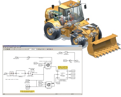
With model-based design, engineers create a block diagram of their design which can be manipulated and tested as many times as necessary within the program. Once a model has been created, it can be passed on to other engineers who can add their system models to test the interaction between the systems.
If, for example, a company has a wheel loader it is designing for a material handling application, the vehicle designers will want to look at the mecahnical, hydraulic and engine systems. Engineers can create a simplistic diagrams of their systems, including the controls, within the software and bring their designs together to create a larger overall model. Simulations can be run of the larger model to see how all of the systems will interact with one another.
Wensi Jin, Industry Manager, Automotive - North America and Asia Pacific at MathWorks, says this is what sets model-based design apart from traditional simulation software, which tends to focus on one thing. “It’s one environment in which engineers from different disciplines can examine the design from different perspectives,” he says. Instead of having one simulation tool for engine systems and another for hydraulics, both systems can be designed and simulated in the same software program.
How it works
System models are created by dragging predefined blocks of functions commonly used in system modeling, such as algorithmic and structural blocks, into the software’s workspace. Users can customize the predefined blocks to their specifications as well as create new ones that can be saved in the library. Lines are then drawn between the blocks, establishing a mathematical connection that turns the interconnected blocks into a functioning system.
Engineers can also organize their system models into hierarchies, creating subsystems by capturing the blocks and signals that make up the subsystem in a single block. This subsystem block can then be plugged into a larger system model, have its contents hidden to protect intellectual property (see sidebar, pg. 47), or simply be saved for use at a later date, as was the case with Caterpillar Inc.
Caterpillar Inc., Peoria, IL, needed to place a powertrain system normally used in off-highway equipment into a small locomotive. The system consists of a diesel engine, an automatic mechanical transmission, axles and a final drive. The mechanical hardware for this multi-part system had previously been designed while the control system had to be designed for the new vehicle application.
To speed up development, Caterpillar engineers employed model-based design by reusing component models that had previously been developed and stored in a library. Reusing models enabled engineers to complete the system model and control development within six weeks. Using a system model which included the engine, transmission, driveline as well as the vehicle, Caterpillar engineers could optimize the control parameters based on the intended driving conditions, which shortened the time required for tuning in the field during the commissioning phase of the system.
Easing design complexity
Being able to design and test several system models within a single environment helps ease the design process. Engineers can see how systems will interact with one another, and make changes to individual systems or the overall system model as necessary without ever having to use another program.
Jin says this is especially helpful when designing for the commercial vehicle industry. “Nowadays the machines tend to be very complex, multi-domain systems and to design them ideally you want to have an environment where all these engineers can look at the same model,” he says.
MathWorks' software makes it easier to optimize an entire vehicle instead of optimizing one system at a time. “If you look at one thing in isolation, you may design the perfect engine,” says Jin, “[and] you may design the perfect hydraulics system, but their operating envelopes don’t really line up.” Model-based design allows the engine engineers and the hydraulics engineers to look at one model that includes the engine system and the hydraulics system, and examine how they will function together.
Manipulating designs and doing more up-front simulation within the software gives engineers confidence their designs will work and be validated, so that once they reach the physical prototype stage, there will be fewer kinks to work out.
MathWorks’ software provides full-vehicle testing capabilities, as well. According to Jin, this is helpful when designing off-highway vehicles because their maneuvers are more complex and use a lot of components on a vehicle at the same time. The engine, hydraulics and mechanical systems may all be used in one maneuver. “This complexity in maneuvers requires people to do a lot more up-front due diligence to understand how the design of the hydraulics system may be impacted and how the engine system may be impacted,” says Jin.
Putting a virtual vehicle through various complex maneuvers shows how its systems will function in the real world. Jin says using the software to do initial studies enables the engineers “to look at the systems on a vehicle level, and figure out if there are errors such as a lack of hydraulic capacity or a lack of engine output.”
Saving time and money
While developing their next generation 20T Excavator Control Valves, HUSCO Intl., Waukesha, WI, saw a 50% reduction in development time using MathWorks’ model-based design software. The company’s engineers were able to design, model and validate their control system in about three months as opposed to the usual seven.
Once the engineers created a system model of the mechanical hydraulics and their controller, they were able to automatically generate code by using Simulink Coder. This add-on product from MathWorks generates and executes C and C++ code from system models made in Simulink, and thus helps speed up the design process. In the past, HUSCO’s engineers had to manually write code for control systems, which was time consuming, especially if there were problems or multiple design iterations.
Engineers were then able to test the accuracy of their design by feeding the code generated from the model into another Simulink add-on called Rapid Control Prototyping. Jin says this system, also known as xPC Target, is basically a PC with IO cards dedicated to running code. Using the code generated from the model, xPC target acts as the controller inside the vehicle to validate the controller’s accuracy. This allowed the engineers to safely debug and fine tune their design before putting an actual controller in the excavator.
Being able to virtually validate the system model and its code reduced the number of physical prototypes, as well. Since so much of the design and simulation work was done within the software, there was no need to create a physical prototype until closer to the end of the design process when engineers were fairly confident their design would function accurately.
Jin says physical prototypes are still an important step in the process because it’s crucial to physically validate the performance as well.
He also notes that testing and validating a design before the physical prototype stage means there is a better chance the design will work the first time once a prototype is made. “As you do simulation you’re able to see a lot of the design efficiencies and be able to figure out errors and fix those errors,” says Jin. “So there’s less debugging when you go to prototype.”


