Seals—while often small in size—can play a major role in the performance and reliability of fluid power systems. Like any component, the composition of a seal is an integral factor. Also important is the balance the seal must strike between leakage and friction—too much of either and the seal, along with the system in which it’s integrated, will wear and not perform as desired.
“All seals have to leak,” explained Chuck White, Director of Commercial Development at Hallite Seals International, during the December Fluid Power Industrial Consortium (FPIC) seminar on sealing technology in fluid power applications (learn more, 20981288). “It’s called boundary lubrication because we have to keep some kind of oil [on the] sealing lip otherwise [it will] burn up [due to] friction. We call it acceptable leakage.”
However, excessive amounts of lubrication are considered a leak, while an inadequate amount will lead to friction, heat and wear occurring. “We have to balance the right amount of fluid that gets by [the seal],” he said.
Considerations for seal designs
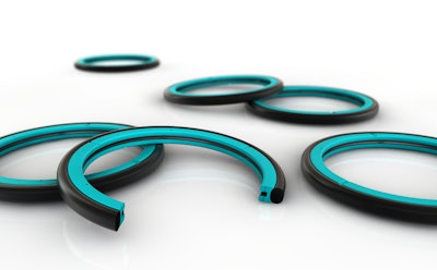
According to White, there are four primary elements to consider when choosing a seal design, such as a U-Cup—the most commonly used type of rod seal in the industry for hydraulic cylinders: preload, groove fill, geometry and materials. 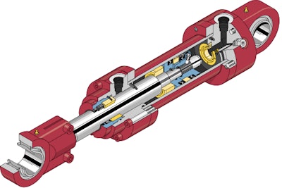 System Seals Inc.
Preload, he explained, is the need to apply a type of spring load when installing the U-Cup into a groove at zero pressure in order to prevent leakage. “We have to predict what that spring load needs to be because we also have to look at when that part starts seeing pressure. We can’t have too much preloading in the beginning.”
This is because as pressure is applied, the seal starts to deform. At the far extreme of 10,000 psi (689.5 bar), the seal will be flat on the rod and cause friction to occur. U-Cups are dynamic seals, which means they seal according to the amount of pressure present. To ensure the right balance of sealing and friction is achieved, determining the correct amount of preload is vital. “It’s a balancing act…there’s no formulation where you say ‘with this profile you do this, and with this one you do this,’” said White. “It’s something over the years we’ve been able to develop, but it’s different for every application.”
Material choice is an especially important aspect of the seal design, as its ability to overcome stick slip and its interaction with fluids used in the hydraulic system are key. White said softer materials tend to be stickier, so a harder material is generally desired as it will produce less friction. However, it shouldn’t be too hard as that will have an effect on the sealing capabilities.
Fluid interaction is particularly important today with the increasing desire of some manufacturers to use environmentally friendly fluids. “Urethanes especially tend to not like some of those, so we have to be careful to look at the compatibility,” explained White. “Incompatibility results in swell, friction [and] failure.”
He said the most common material Hallite uses is polyurethane due to the balance of benefits it provides regarding seal ability, wear, extrusion resistance and cost.
Hydrolysis/chemical resistance is an important factor for material consideration, as well; depending on whether it’s ether or ester based will determine the fluids and systems for which the material is best suited. Ester-based materials, for instance, are capable of interacting with some of the environmentally friendly fluids currently available and thus better suited for those applications in which they are being utilized.
The biggest takeaway said White, is the need to understand the application in which the seal will be used in order to make the best decision on what materials to use. “Not all materials are suitable for all applications.”
Surface finish is another key factor that needs to be considered, he said. It used to be that a smoother finish on the mating sealing surface was desired to prevent corrosion. However, that mindset has shifted toward having some roughness to ensure boundary lubrication. “If you have a nice smooth surface, the oil’s got nowhere to go,” explained White. Conversely, if you have too rough a surface, the seal lip could tear. So again, finding the right balance—between a not too smooth and not too rough surface—is critical.
“Surface finish needs to be discussed in the same breath as frictional analysis as this can have a direct impact on frictional force and the sealing interaction,” said Tim Girardi, Application Engineer at System Seals Inc., during the FPIC seminar.
He cited a case study in which a customer wanted System Seals to investigate four different rod groups and identify the best surface finish of them for its application. “This case study looked at surface finish parameter combinations with respect to wear,” Girardi explained. “The design of experiment focused on the most statistically significant surface finish parameters to reduce wear.”
The company developed a correlational model between seal changes and surface finish parameters to properly predict the best surface finish for optimal seal performance. By doing so, Girardi said an optimized solution was found for the customer. In addition, the project laid out the foundation for System Seals to be able to give surface finish recommendations across the board. 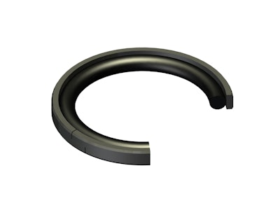 The Hallite 714 High-Pressure Compact Double Acting Piston Seal features a profiled nitrile rubber energizer which responds quickly to pressure changes for excellent sealing characteristics under a wide range of pressure conditions (learn more, 12062317).Hallite Seals Americas Inc.
Finding the optimal solution
As with any design, testing and analysis is critical to ensuring optimized performance. Girardi spoke during the seminar about analyzing seal component interactions in order to maximize performance and reliability. “How we analyze these interactions to achieve that desired interaction is through a sequential process that starts by identifying the pertinent application parameters…most important to seal and ultimately cylinder design,” he said.
These parameters, abbreviated as STAMPS, are:
- Size of the cylinder
- Temperature—operating as well as ambient
- Application—is it rotary, linear, are there other important factors to take into consideration
- Media or fluid being utilized
- Pressure of the system
- Speed
From there, he said the next steps are to conduct side load analysis—during which material selection is also considered—followed by extrusion analysis, and finally friction analysis. “All together this allows us to optimize the sealing components based on their interactions to each other.”
Analyzing side load, focusing particularly on the interaction between the guide band and the rest of the cylinder such as the rod and cylinder body, helps to ensure proper guidance and eliminate metal-to-metal contact. It can also provide valuable information that can be used through the rest of the analysis process, said Girardi.
He explained that standard methods of determining side load evenly distribute it across the predicted area of the guide band. If the loads are too high, it’s determined that increasing the height of the guide band will then increase the projected area on which the load is being distributed. “This oversimplified approach is often used because it’s fast [and] easy,” he said. “The problem is, this assumes a side load. It ignores the fact the side load comes from the cylinder itself, computes linear results and completely ignores the angle of contact between the rod and guide band.”
To best determine side load and the other factors in the analysis process, he said methods include experimentation, hand calculations, finite element analysis (FEA) and proprietary calculators. While experimentation can provide the desired results, Girardi said it is time consuming and requires set up and testing for every individual application. Hand calculations also have the same drawbacks. FEA requires expensive software and can still be time consuming but does make it easier to change design parameters as necessary.
Proprietary calculators, he said, are the preferred method for System Seals. “It combines the ease of making changes like the FEA software but delivers the results in a fraction of the time... minutes versus hours, sometimes even days in some cases,” he said. “This removes the possibility for set up or user errors that the other forms are plagued by.”
Girardi explained that System Seals developed its proprietary calculator to allow for faster input and results based on entering in the STAMPS information. This software also removes the setup variation that often exists from running FEA, giving much more consistent and accurate side load calculations.
These can be beneficial, as well as in-house testing procedures, when testing aspects for which either a standard does not exist or the standard does not take enough into account.
As noted earlier, chemical compatibility and the fluid being used in an application are important aspects of the material selection process. Girardi said many standards for fluid compatibility testing are only 24 hours or 7 days; at most they are 28 days. However, this does not necessarily provide an accurate picture of long-term compatibility.
He provided the example of testing System Seals conducted of a seal within a certain type of fluid. After 7 days everything looked fine. The company decided to run the test out over the course of 90 days—a point it has determined to be a statistical enough sampling to eliminate as many false positives as possible—and found that suddenly the seal and fluid were not as compatible as originally thought.
Determining what is considered acceptable leakage—a question the industry has been battling for years, said White—is a factor of seal designs for which there is no currently known standard. And what is considered acceptable in one industry may not be so in another.
“How [do we] compare visually to what actual leakage conditions are, what’s considered acceptable? What rod seals perform the best and how can we best understand their leakage to improve seal design? It’s application based, but obviously we don’t want to see any outboard leakage,” said White.
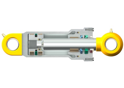 Proper seal design is integral to ensuring the performance and reliability of fluid power components, such as hydraulic cylinders.SKF Sealing Solutions
He said Hallite has adopted a retired SAE standard for some general guidance, but it doesn’t provide a whole picture. To overcome this, the company has teamed up with the Milwaukee School of Engineering (MSOE) to develop a rod seal endurance test rig. Typically when testing cylinder rod seals it requires a lot of energy and mechanical resistance. “We wanted to come up with a way to test just the rod seal, and we were able to do so with minimal energy,” said White.
Capable of testing 16 rod seals simultaneously, the test rig offers a variety of operating conditions to be taken into account such as stroke speed and length, pressure and temperature, and various fluids. “It opens the door for us to not only do testing but [also] start doing some statistical sampling,” he said.
“With this system, we can start assessing within the industry what customers like,” White continued. If there is a particular type of seal customers like, Hallite can then test its leakage and find out if it is acceptable or not to customers, and from there determine based on the application what type of seal works better.
“Now we can start talking with data,” he concluded. “This is allowing us to at least talk to customers and say ‘this is how much this seal leaks, is that okay?’ We are going to keep working on a standard for acceptable leakage.”










![8042 23 Dsc2132 Copy Bearb Cmyk Hintergr Unscharf 02 (002)[1]](https://img.oemoffhighway.com/files/base/acbm/ooh/image/2023/10/8042_23_DSC2132_copy_bearb_CMYK_Hintergr_unscharf_02__002__1_.653bdc00097dc.png?ar=16%3A9&auto=format%2Ccompress&fit=crop&h=135&q=70&w=240)
